Coursework Projects
Rocket-LaunchedEgg PayloadGlider
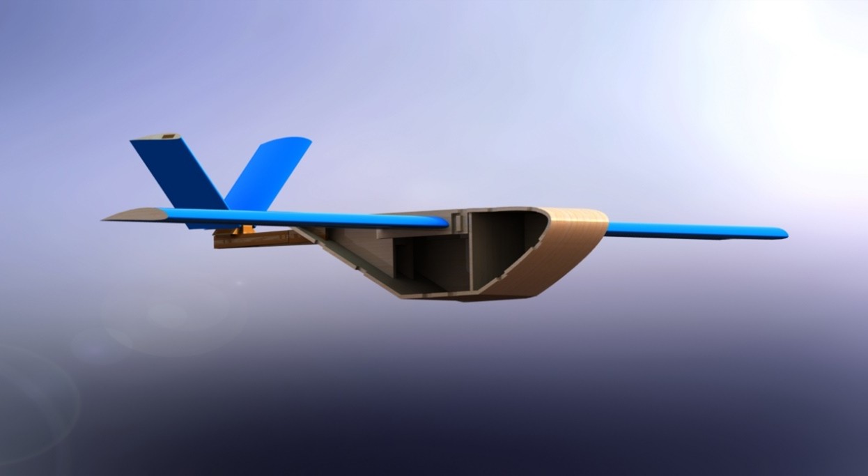
Designed and developed a small rocket-launched fixed-wing glider capable of carrying and protecting an egg payload. My work covered requirements definition, concept development, CAD modelling, aerodynamic sizing, rocket motor selection, V-tail design, payload protection, final renders, technical drawings and manufacturing documentation.
Key Details
- Date: 2024
- University: Swansea University
- Module: EG-165 Coursework 3
- Project type: Rocket-launched fixed-wing glider
- Role: Requirements, CAD, aerodynamic sizing, final design, renders and technical drawings
- Payload: One egg
- Launch method: Hobby rocket motor
- Selected motor: Klima C6-5
- Final aerofoil: SD7037 at 150% thickness
- Final wingspan: 750 mm
- Final length: 419 mm
- Wing chord: 75 mm
- Tail chord: 56.12 mm
- Estimated take-off distance: approximately 1.5 m
- Estimated take-off velocity: approximately 11 m/s
- Estimated ideal glide distance: approximately 1.3 km
Overview
This project involved the design of a small-scale rocket-launched glider capable of carrying an egg payload, taking off from a short runway, flying beyond the required distance and landing without damaging the payload.
The task combined aircraft configuration design, aerodynamic sizing, rocket motor integration, payload protection, CAD modelling and production-ready technical drawings.
My work focused on turning the coursework brief into a complete engineering design package. I defined the design requirements, developed the initial concept, produced the CAD design, carried out performance and sizing calculations, selected the aerofoil and rocket motor, created the final glider configuration, produced renders and generated the technical drawing package for manufacture and assembly.
Design Requirements
- Securely carry one egg payload.
- Mount and safely retain a hobby rocket motor.
- Include a rocket motor compartment with a bulkhead or push-plate.
- Use balsa / spruce wood and solar film aerofoil covering.
- Keep wing area no greater than 0.1 m².
- Include skis or fixed landing struts to interface with the runway grooves.
- Protect the payload from launch through landing.
- Keep the rocket and payload secure during flight.
- Use a wingspan sufficient for lift and stable glide, not exceeding 1 m.
- Minimise weight to maximise lift within the wing area constraint.
- Size skis to fit the runway groove arrangement.
- Take off within the 4.5 m runway length.
My Contribution
- Defined the project requirements table used to guide objective design decisions.
- Developed the initial glider concept with an aerodynamic nose, high-mounted wing and rocket placement aligned close to the aircraft centre of mass / centre of lift.
- Identified key structural and stability issues in the first concept, including tail-boom loading, T-tail support and manufacturability.
- Iterated the design into a more practical final aircraft configuration.
- Produced the CAD model and final aircraft layout.
- Developed the amalgamated initial design using a high-mounted wing, curved fuselage and V-tail arrangement.
- Selected and justified the SD7037 aerofoil at 150% thickness for low-speed aerodynamic performance and practical manufacture.
- Carried out aerodynamic and performance calculations covering aerofoil selection, rocket motor selection, take-off properties, wing sizing, tail sizing, V-tail geometry, centre of gravity, neutral point and static margin.
- Selected the Klima C6-5 rocket motor based on calculated launch performance.
- Produced final renders and visual design outputs.
- Created the final technical drawing package for manufacture and assembly.
- Produced the final Bill of Materials and manufacturing documentation.
Concept Development
My initial concept used a streamlined fuselage, high-mounted wing and high rocket position to help align the thrust line close to the centre of mass and centre of lift. This was intended to reduce unwanted pitching moments during powered launch and improve flight stability.
The concept also explored a slight dihedral arrangement to improve lift characteristics and landing clearance. During design review, I identified several weaknesses that needed further iteration, including the structural challenge of supporting the tail on long booms, the stability requirements of the tail and the manufacturing difficulty of using wing angles that would improve performance without making the design overly complex.
This concept was later developed into the final design, with the main lesson being that aerodynamic efficiency had to be balanced against structural simplicity, manufacturability and payload protection.
Amalgamated Initial Design
I created the amalgamated initial design as the first integrated aircraft layout. This design combined the strongest features from the early concepts into a single configuration that could be refined through calculation and CAD development.
The initial integrated design used:
- A cambered aerofoil concept to improve lift characteristics.
- A high-mounted wing for stability and clean packaging.
- A V-shaped tail to improve stability and reduce drag.
- A curved fuselage to improve the aerodynamic profile and soften landing impact.
- Rocket placement aligned as closely as possible with the centre of mass and centre of lift.
This design became the basis for the final glider configuration and helped define the direction for the CAD model, aerodynamic sizing and manufacturing drawings.
Aerodynamic and Performance Work
I carried out the aerodynamic and performance calculations used to size and validate the glider. These calculations covered aerofoil selection, rocket motor selection, take-off properties, wing dimensions, tail design, V-tail construction, centre of gravity, neutral point and static margin.
The selected aerofoil was the SD7037 because it provided the strongest lift-to-drag performance among the considered options while operating at a low angle of attack. I used the SD7037 at 150% thickness to improve leading-edge camber, support low-speed flight and make the aerofoil more practical to manufacture.
Final calculated wing dimensions:
- Wingspan: 750 mm
- Chord length: 75 mm
- Taper ratio: 1
- Sweep: no sweep
- Wing area: 5.625 × 10^-2 m²
The final rocket motor selected was the Klima C6-5 because the calculations showed it could launch the glider within approximately 1.5 m while maintaining a suitable climb profile.
Final Design
The final design used the SD7037 aerofoil at 150% thickness for both the main wing and tail, a curved front fuselage, a V-shaped tail, a lightweight built-up structure and a secure rocket mounting arrangement.
Final specification:
- Wingspan: 750 mm
- Total length: 419 mm
- Wing chord length: 75 mm
- Tail chord length: 56.12 mm
- Aerofoil: SD7037 at 150% thickness
- Rocket motor: Klima C6-5
The final design was developed to balance aerodynamic performance, payload protection, launch stability, low mass and manufacturability.
CAD and Technical Drawings
I produced the CAD design and final technical drawing package for manufacture and assembly. The drawing package included the overall glider assembly, wing assembly and wing box, rocket assembly, tail assembly and fuselage assembly.
The drawings included third-angle projection views, assembly views, exploded and detailed component views, millimetre dimensions, tolerances, surface finish notes, part callouts, Bill of Materials references, manufacturing notes, rocket bay details, egg compartment details, aerofoil geometry, wing box geometry, tail assembly geometry and fuselage manufacturing details.
Overall Glider Assembly
Full aircraft assembly drawing showing the glider layout, rocket bay, egg compartment, main wing, V-tail and part callouts.
Wing Assembly & Wing Box
Wing structure drawing showing the 750 mm span, 75 mm chord, SD7037 aerofoil geometry, wing box and spar/slat arrangement.
Rocket Assembly
Rocket mounting design for the Klima C6-5 motor, including push-plate, baseplate and rocket bay integration.
Tail Assembly
V-tail drawing package showing the tail stick, SD7037 tail aerofoils, connector parts, arm links, pins and assembly geometry.
Fuselage Assembly
Fuselage manufacturing drawing showing the curved nose, payload bay, rocket bay, wall sections and assembly interfaces.
Bill of Materials
I produced the final Bill of Materials and manufacturing documentation for the aircraft. The BoM captured the key materials and purchased parts required for the glider build, including balsa sheet, spruce sheet, balsa trailing edge stock, obechi strip, solar film, cyanoacrylate adhesive and the Klima C6-5 rocket motor.
Key Metrics
Wingspan
750 mm
Final main wing span after aerodynamic sizing.
Length
419 mm
Total final glider length.
Aerofoil
SD7037
Selected for high lift-to-drag performance at low-speed flight conditions.
Motor
Klima C6-5
Selected hobby rocket motor for launch performance.
Take-off Distance
~1.5 m
Estimated launch distance within the 4.5 m runway requirement.
Wing Area
5.625 × 10^-2 m²
Final calculated wing area within the coursework limit.
Take-off Velocity
~11 m/s
Estimated take-off velocity from performance calculations.
Ideal Glide Distance
~1.3 km
Ideal calculated glide distance after motor burnout.