Dissertation Projects
RotatingDetonationEngineCFD
Numerical dissertation investigating whether a computationally constrained ANSYS Fluent model could reproduce key detonation behaviour in a rocket-mode rotating detonation engine. The study combined NASA CEA benchmarking, one-dimensional shock tube validation, mesh and CFL sensitivity studies, CHEMKIN hydrogen-oxygen chemistry, a pressure-dependent inlet UDF and a three-dimensional AFRL-based annular combustor simulation.
Key Details
- Date: 2026
- University: Swansea University
- Project type: Individual dissertation / final paper
- Topic: Rotating detonation engines for space applications
- Software: ANSYS Fluent 2025 R2
- Chemistry: Stoichiometric hydrogen-oxygen mixture
- Combustor: AFRL-based annular RDE geometry
- Numerical methods: 1D shock tube and 3D transient CFD
- Validation method: NASA CEA Chapman-Jouguet detonation properties
- Chemical kinetics: O Conaire hydrogen oxidation mechanism
- Solver: Density-based transient reacting flow solver
- Inlet model: Pressure-dependent user-defined function
- Main outcome: Initial rotating detonation wave generated, but not sustained due to inlet backflow
Overview
This dissertation investigated the numerical modelling of rocket-mode rotating detonation engines for space propulsion applications. Rotating detonation engines are pressure-gain combustion systems where one or more detonation waves continuously travel around an annular combustor.
The aim was to determine whether a computationally constrained ANSYS Fluent model could reproduce the key qualitative features of detonation behaviour in a simplified rocket-mode RDE. The study used a stoichiometric hydrogen-oxygen mixture, NASA CEA Chapman-Jouguet benchmarking, a one-dimensional shock tube validation model and a three-dimensional annular combustor geometry based on the Air Force Research Laboratory RDE configuration.
The final model successfully generated an initial detonation wave in the annular combustor, with pressure levels comparable to theoretical CJ values. Sustained rotating detonation was not achieved because backflow across the inlet boundary prevented continued reactant injection.
Research Challenge
- Rotating detonation engines involve coupled shock waves, rapid chemistry and highly transient pressure fields.
- Accurate RDE simulations normally require fine meshes, very small timesteps and high computational resources.
- The ANSYS Student environment imposed practical limits on cell count, solver runtime and troubleshooting speed.
- The project therefore focused on a computationally constrained model capable of reproducing qualitative detonation behaviour rather than a fully resolved experimental-grade RDE simulation.
- A key modelling difficulty was representing injector behaviour without modelling the full upstream plenum and injector geometry.
- The main technical risk was whether the simplified inlet boundary could maintain reactant injection after the initial detonation wave formed.
My Work
- Researched pressure-gain combustion and the operating principles of rotating detonation engines.
- Reviewed experimental and numerical RDE literature, including AFRL-style annular combustor studies.
- Defined the dissertation scope around rocket-mode hydrogen-oxygen RDE modelling.
- Used NASA CEA to calculate theoretical Chapman-Jouguet detonation properties for the H2/O2 mixture.
- Built and tested a one-dimensional shock tube model to validate solver behaviour.
- Conducted mesh sensitivity and CFL studies to select a practical setup for the 3D simulation.
- Created a simplified AFRL-based annular combustor model suitable for computationally constrained CFD.
- Selected and implemented a CHEMKIN hydrogen oxidation mechanism.
- Developed a pressure-dependent inlet UDF concept with blocked, subsonic isentropic and choked-flow injection regimes.
- Set up transient reacting-flow simulations in ANSYS Fluent.
- Generated and analysed pressure contours, wave propagation behaviour, inlet mass-flux behaviour and backflow failure modes.
- Identified why the 3D detonation failed to sustain and proposed future improvements to injector modelling, ignition sensitivity and geometry fidelity.
Background
Rotating detonation engines use detonation combustion rather than conventional deflagration combustion. In a conventional rocket engine, propellants burn through a process that approximates constant-pressure heat addition. In an RDE, the detonation wave produces a pressure rise inside the chamber, creating a pressure-gain combustion process.
This makes RDEs attractive for space propulsion because higher combustion efficiency and reduced upstream pressure requirements could reduce engine mass, turbomachinery complexity and overall propulsion system size.
Methodology
The methodology was structured around progressively validating the numerical model before attempting the full 3D combustor simulation.
NASA CEA Benchmarking
NASA CEA was used to calculate theoretical Chapman-Jouguet detonation properties for a stoichiometric hydrogen-oxygen mixture. These values provided a benchmark for the Fluent simulations.
- CJ pressure: 20.4 MPa
- CJ temperature: 4137.8 K
- Detonation velocity: 2958.8 m/s
- Pressure ratio: 20.159
One-Dimensional Shock Tube Validation
A one-dimensional shock tube tested whether the solver, chemistry model and timestep settings could generate and propagate a detonation wave before moving to the full annular combustor.
Mesh Sensitivity Study
Mesh sizes of 0.5 mm, 1.0 mm, 1.5 mm and 2.0 mm were tested. A 2 mm mesh was selected because it produced similar wave-speed accuracy to finer meshes while significantly reducing the number of required timesteps.
CFL Study
A CFL value of 0.4 was selected because it remained within the literature-recommended range and gave consistent wave-speed behaviour without relying on pressure results that appeared to be numerical artefacts.
Three-Dimensional RDE Simulation
The final 3D model used an AFRL-based annular combustor geometry with outer diameter 154 mm, inner diameter 139 mm, combustor length 100 mm, a premixed hydrogen-oxygen inlet, pressure outlet and ignition patch of high-pressure, high-temperature combustion products.
Numerical Modelling Workflow
Numerical Setup
The final solver setup used a density-based transient formulation in ANSYS Fluent. A density-based approach was chosen because it is more suitable for compressible shock-dominated flows.
- Density-based solver
- First-order implicit transient formulation
- Inviscid flow model
- Species transport with finite-rate chemistry
- CHEMKIN hydrogen oxidation mechanism
- Roe Flux Difference Splitting scheme
- Second-order upwind spatial discretisation
- CFL number: 0.4
- Premixed mass-flow inlet controlled by a pressure-dependent UDF
- Pressure outlet at 1 atm
- Initial nitrogen-filled domain
- Ignition patch at 50 atm and 3442 K
Pressure-Dependent Inlet UDF
The inlet UDF was designed to approximate injector behaviour without modelling the full upstream plenum. It switched between three regimes based on chamber pressure:
- Blocked injection: chamber pressure exceeds plenum stagnation pressure, preventing inflow.
- Subsonic isentropic injection: chamber pressure is below plenum pressure but above critical pressure.
- Choked injection: chamber pressure falls below critical pressure and mass flux becomes independent of downstream pressure.
- A scaling factor accounted for the difference between total injector orifice area and the simplified full inlet plane.
- A value of 0.2 was used for the injector-to-inlet area ratio.
Results
The one-dimensional shock tube simulations confirmed that the numerical setup was capable of producing and propagating a detonation wave. With the selected 2 mm mesh and CFL value of 0.4, the shock tube produced a peak pressure of approximately 16.1 MPa and a wave speed of 2469 m/s.
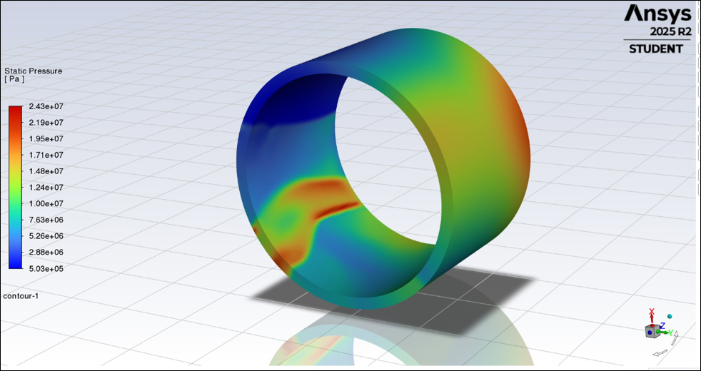
The 3D annular combustor simulation successfully generated an initial high-pressure detonation wave after ignition. The peak pressure reached approximately 24.3 MPa, which compared favourably with the NASA CEA Chapman-Jouguet pressure of 20.4 MPa.
Sustained rotating detonation was not achieved. The wave decayed after the initial reactant supply was depleted, and inlet analysis showed negative mass flux confirming backflow across the inlet boundary.
Mesh Sensitivity Study
Wave-speed comparison across mesh sizes, showing that a 2 mm mesh provided acceptable accuracy while reducing computational cost.
Ignition Zone
High-pressure and high-temperature patch used to initiate the detonation wave inside the annular combustor.
Initial Detonation Formation
Pressure contour showing the initial high-pressure detonation structure after ignition.
Wave Propagation
Successive pressure contours showing limited circumferential propagation of the detonation wave.
Inlet Backflow
Mass flux behaviour indicating combustion product backflow through the inlet boundary.
UDF Failure Mode
Pressure contours after inlet blocking prevented fresh reactant injection and caused the detonation wave to collapse.
Failure Mode - Inlet Backflow
The 3D simulation did not fail because the solver or chemistry model could not create a detonation wave. The one-dimensional validation proved that the density-based solver and CHEMKIN mechanism could produce sustained detonation under the same operating conditions.
The limiting issue was the inlet boundary condition. Once high chamber pressures developed, the pressure-dependent UDF entered the blocked-flow regime. This prevented continued reactant injection and allowed combustion products to backflow through the inlet plane.
This result highlighted the importance of accurate injector modelling in rotating detonation simulations. A simplified premixed inlet can reproduce initial detonation behaviour, but sustained RDE operation requires a more robust injection model or a more realistic injector/plenum geometry.
Limitations
The model was intentionally computationally constrained. The ANSYS Student license limited computational resources, and the three-dimensional simulation required approximately 128 hours of runtime.
The selected 2 mm mesh reduced computational cost, but detonation modelling literature suggests that sub-millimetre resolution is typically required to resolve detonation reaction zones and shock gradients accurately. The model should therefore be interpreted as a qualitative demonstration of detonation behaviour rather than a quantitatively exact prediction of RDE performance.
Future Work
The next stage would be to improve the inlet UDF and injector boundary conditions so reactant injection can recover after the detonation wave passes. Additional simulations should investigate ignition patch size, ignition location and thermodynamic state to determine their effect on detonation formation and stability.
A more complete model would include realistic injector and nozzle geometries rather than a simplified premixed inlet. Higher computational resources would also allow finer mesh resolution, longer runtimes and more detailed wave-structure analysis.
Key Metrics
CJ Velocity
2958.8 m/s
Theoretical Chapman-Jouguet detonation velocity from NASA CEA.
CJ Pressure
20.4 MPa
Theoretical Chapman-Jouguet pressure for the H2/O2 mixture.
1D Wave Speed
2469 m/s
Simulated shock tube wave speed, approximately 83% of CJ velocity.
1D Peak Pressure
16.1 MPa
Shock tube peak pressure, approximately 79% of CJ pressure.
3D Peak Pressure
24.3 MPa
Peak pressure from the annular combustor simulation after ignition.
Mesh Size
2 mm
Selected mesh resolution for computationally constrained 3D simulation.
CFL
0.4
Selected CFL number for transient density-based simulation stability.
Runtime
128 hours
Approximate runtime for the final 3D simulation under student-license constraints.